
|
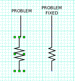
Making the resistor one step wider or narrower will get rid of the
problem of it's endpoint being half way between a pair of grid lines. It the grid is set too coarse this may make the resistor wider or narrower than desired, so the fix is to adjust the grid lines closer or further apart. ![[ see attached screenshot-2 ]](pngMOv8BZ9odb.png) Arv _._ On 12/28/2010 03:23 PM, Chris G wrote: On Tue, Dec 28, 2010 at 05:05:40PM -0500, Michael Ross wrote:If I place a resistor, and then a zig zag line, then I move an end of the zzline near an end point of the resistor the resistor get a red outline indicating there is a connection between the "grips," if I let the line go while the red outline is present then when I move the resistor the line tracks it. If I move the line the resistor does not track the line. The four extents for the resistor symbol snap to the grid. If you want the center of the resistor to snap exactly just so to the grid, you will have to size the grid so that when you place a corner the leg of the resistor is on a grid line.With the grid the way I have it I can't even get to connect the line to the resistor because the centre line of the resistor is between grid lines. I have to turn 'Snap to Grid' off to connect the line to the resistor, then turn it back on and it acts as you say.Sorry you don't like this functionality, but it makes sense to me, the grid is essentially arbitrary so there is no particular reason why the symbols should be constrained to it. If you really need it to be just so then you can control the size and shape of the symbol and grid to produce the result you are after. I prefer the more general solution that is implemented where any symbol of any size has connection points to which a line will glom onto it and move with the symbol.That's OK if *every* symbol you want has a ready made representation with connection points, however I've found I always want quite a few extra symbols (e.g. in the current circuit I'm drawing I have several multiway switches) and then it begins to get clumsy. Maybe I simply need to reduce the grid size so that sensibly small resistors are two grid lines wide and thus their centre lines are on a grid line.If you can make a good case for the function you want, then perhaps the developers will be able to implement it. or you can implement it yourself. This is free open source software so you can learn to program it to do as you wish.Of course, but it's a long term way of getting what I want. It's always good to ask knowledgeable people on a list such as this because very often there are ways to get what one wants which are not immediately obvious. Thanks for all the help. I'm off to play some more and see if I can get closer to what suits me. |
Attachment:
Screenshot-2.png
Description: PNG image